Yaesu 5400 Rotator Controller Light Replacement Notes

The lights on the direction indicators died long ago. Without the lights the unit did not seem complete, and operating at Field Day now required additional light.

I opened the case to see if it was like the Hygain rotor controller where I had already replaced the bulb with LEDs, and found it to be similar. It may not look that way, but from the perspective of illumination it is.

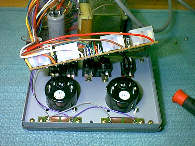
The circuit board is held to the face by screws that actually screw into the backs of the meters. You will need to remove the screws and pull the circuit board back to have the room you need. I didn't disconnect any wires at this stage.

I measured the voltage feeding the lights and was a little surprised to find about 15 Volts AC.

I removed both of the light circuit boards and found this unique looking light bulb.

Here is the schematic of the circuit I wound up using. There is no magic here. Depending on the LEDs you use your resistor value may be different.

This shows how I wired the circuit. Kind of a flying dead bug style. The resistor shown is not the one I wound up using, but the circuit looks the same.

Here is the circuit wired into the controller. The black thing is just in there to make it easier to see. It is not part of the rotor controller circuit.

It is always a good idea to check that everything works before putting it all back together. Remember LEDs (even wide angle ones) are built to project their light out the end to compensate for this I made sure they pointed down towards the meters. I used white LEDs, but there is no reason you couldn't use another color.... Maybe match the color of your rig's display?

Here is the completed unit. You can tell there are two LEDs over each meter as opposed to a single bulb. I believe you need at least two if you want to completely illuminate the meters.
Home


